
Pipe Rehabilitation Replacement NASA Rocket Stand 36-112 inch Cooling System
Abstract; Pipe Rehabilitation Replacement of NASA Rocket Stand 36”-112” Cooling System. This slide show provides commentary, photographs and methods utilized for the replacement of a complex piping system used to cool NASA rocket engines as follows:
The NASA Stennis Space Center is America’s premier rocket engine test complex, the NASA center where engines for all manned Apollo (including the moon missions) and space shuttle flights have been tested and where next-generation engines that will once again carry humans into deep space will be tested.
In 2009, Stennis completed 34 years of testing space shuttle main engines used on more than 130 missions. All space shuttle main engines had to pass a series of test firings at Stennis prior to being installed on an orbiter. At Stennis, next-generation engines will be tested including those for cargo flights to the International Space Station and NASA’s new Space Launch System (SLS) which will carry humans deeper into space than ever before.
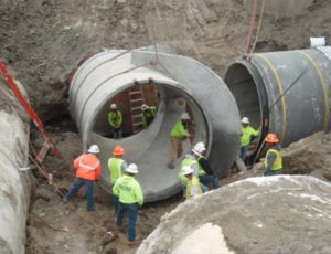
The main components to this project included replacing a high pressure water cooling system including two major multiple outlet header/manifolds. The first manifold is located at a pump station next to a water supply reservoir and the second manifold is located under the rocket stand. The system is powered by 10 very large surplus submarine diesel engines which pressurize the water through 10 each 36” pipe laterals into a single 112” manifold. The manifold feeds a 96” pipeline which extends approximately 4000’ to a second manifold system under the base of the rocket stand. From this point the test stand manifold distributes the water through 16 each 36” pipe 45 degree laterals plus 2 each 66” vertical laterals up into the rocket stand to water nozzles which spray and cool the rocket engines. There were over 238 welded pipe connections including over 40 field fabricated compound miters and many complex fittings needed to assemble the system into the existing structure. All field welding was required to meet the acceptance criteria of ASME Section B31.3 (petroleum refinery piping code) including 100% Radiographic Inspection. Most of the main 96” pipeline was completed while the rocket stand was operable or operating however most of the complex manifold piping was performed during a scheduled shut down for rocket tests with a very tight around the clock schedule.
Several key challenges experienced during the project included 1) pipe drawings created in the 1960’s but inaccessible prior to construction to verify accuracy 2) combining 18 each 36” and 2 each 66” butt welded pipe through 20 independent openings in a 4’ thick concrete slab with very limited clearance 3) Post Weld Heat Treatment (PWHT) was required on many welds within the test stand which exceeded 1” in pipe wall thickness 4) Pipe delivery was very close to the installation schedule and added a further challenge to logistics. The combination of these issues create a mix of difficult conditions which could only be overcome through constant problem solving by all parties. Thankfully the rocket test scheduled subsequent to this updating was able to proceed but with mere hours to spare.